Some Wireless Fundamentals
|
Background. When
teaching about wireless I will express pretty extreme dissatisfaction
with the source materials. While this is true for all networking
resources, it seems even more true for wireless. The two wireless
sources that I have found to be most reliable, and pretty reasonably
reliable are the book by Roshan and Leary, and the book by Bardwell and
Akin. Much of my write-ups rely on these sources as well as some
write-ups within the website of Cisco. I am still working very hard to filter the hype from the reality in wireless and all networking. This is disturbingly difficult to do! Some Radio Frequency Properties. We will start with a brief survey of five main RF - Radio Frequency properties.
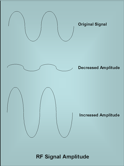
These will be fairly important as we gain insight into the functional capabilities of wireless. Amplitude. Think of how a speaker vibrates as the sound gets louder. It's not dissimilar to compare this to the intensity with which electrons vibrating in an antenna. As amplitude increases, the signals are more likely to show higher signal strength in a receiver. The following diagram illustrates some of the basic representations of amplitude. |

Some typical power levels are illustrated in the
following list.
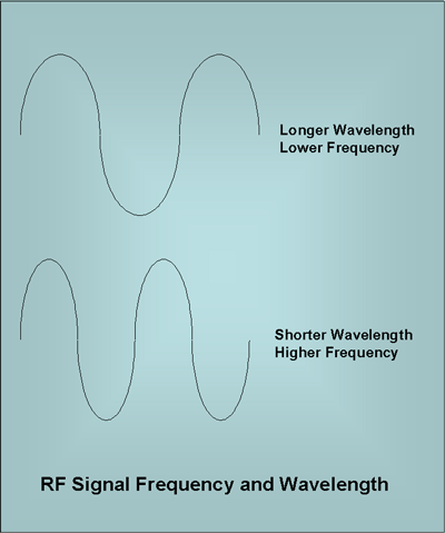
Again, basically the strength of the signal the likelier a receiver will recognize it. High amplitude signals go farther. As a rule of thumb, an 802.11 transmission should use just enough power, but not too much. Frequency and Wavelength. In AC - Alternating Currents have changing amplitude over time. DC - Direct Currents do not change in amplitude over time. Transmission and reception are easier if a signal alternates with a decently regular pattern. The following diagram represents how frequency and wavelength interrelate. |
| If signals alternate at different frequencies
they are less likely to interfere with each other. Though
stations that want to communicate must do so on identical
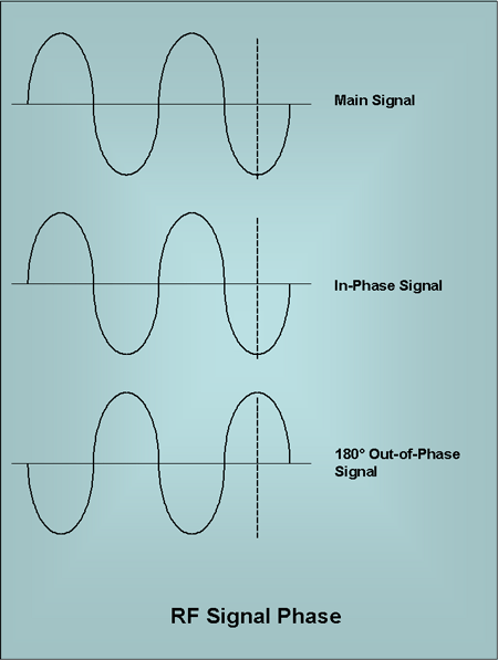
frequencies. Wavelength is usually the distance from a signal's relative to peak to its next, assuming it's regular. It turns out that antenna are most receptive to signals that have a wavelength equal to the length of the antenna's element. It turns out that if you can't match this length then 1/2 or 1/4 the length are the next best choices. Remember, antenna's internal elements are not likely to be the same as the rubber or plastic outer sheath which is invisible to 2.4 or 5.0 GHz RF. We won't get into the computation of wavelengths relative to frequency, though they depend on the medium such as vacuum or air. Phase. Phase is a way to measure the coordination in timing between two or more signals. Phase is measured in degrees, but more like the degrees of a compass or circle rather than a thermometer. If two signals of the same frequency are aligned so that they both reach their peak amplitude at the same time, we say the signals have 0° of phase separation. If the signals are aligned so that one is reaching its peak when the other is reaching it lowest amplitude, we say the signals have 180° of phase separation. All other relationships fall someplace between these two extremes. The following diagram gives a simple illustration. |
| In a WLAN if two signals are in phase their
signals add together increasing the amplitude. If the signals
are 180° out of phase they will cancel
each other. Other combinations have differing impacts. Phase ends up being important when one considers how data is actually transmitted and synchronizing transmissions. In wireless, it can also be important because you might get multipath interference where the phase overlapping of two signals can actually cancel them out resulting in a dead zone. Polarization. Polarization is a fairly abstract concept that has some practical implications. A radio wave can be viewed as being made up of two fields, one electric, the other electric. These two fields are on planes that are perpendicular to each other. The sum of these two fields is called the electromagnetic field. Oscillation derives from energy being transferred back and forth between the two distinct fields. Polarization with respect to antennas refers to whether the antenna is in a vertical or horizontal position. The vertical position is usually used in WLANs. You should think about APs you've seen. The following diagram is an effort to illustrate how radio transmissions don't get received by an antenna with an unaligned polarization. |
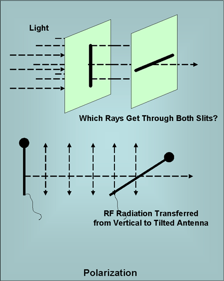
| APs almost always have vertical antenna.
Unfortunately, the NICs in laptops almost always have horizontal
antenna since it isn't really possible to get a vertical antenna
into a PCMCIA card in a small circuit board. We also know
something about how it is desirable to get antenna lengths to match! You may have noticed that PDAs, which usually have vertical antennas often get better reception in some areas than laptops. It might even be worthwhile to orient AP antennas horizontally. Polarization is much more important for long distance point-to-point transmissions. It isn't as important indoors because signals reflect and the NICs antenna are likelier to be in alignment with one of these reflections. Some Problems. The following section overviews a number of potential problems with RF signals. This will mostly be presented in an outline form.
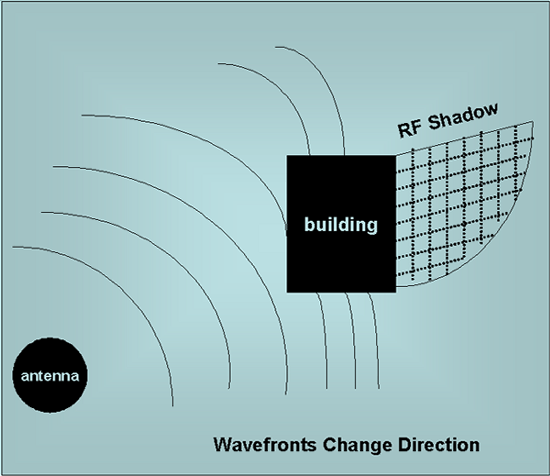
The following image represents diffraction. |
Three Not Easy Pieces. Now we will end this page with three final major pieces of jargon. While you aren't Electrical Engineers, due to FCC regulations on wireless, it is important you know these pieces of jargon. VSWR - Voltage Standing Wave Ratio refers to the backwash that occurs when impedances are mismatched. The ratio refers to the ratio of the impedances of the mismatched devices. You can think of this in terms of having water running into a garden hose with a one inch diameter. Assume the next hose link only has diameter of 1/2 inch. If the water is running with much force you will definitely get some sort of backwash. VSWR measurements are always done a:1 where a is too often not equal to 1. If the ratio is 1:1 then you have a match. A typical mismatch is 1.5:1. An intentional radiator is FCC terminology referring to devices that generate and radiate RF signals. But it refers to all the RF devices, the cabling and connectors, but not the antenna itself. This is shown in the following figure. |
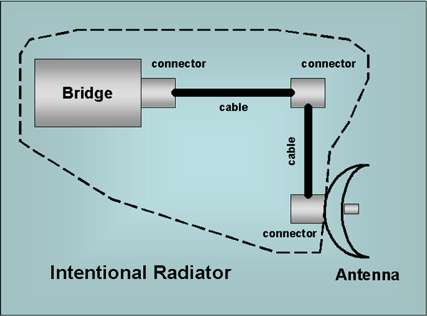
| FCC regulations may refer to the power output of
the intentional radiator. EIRP - Equivalent Isotropically Radiated Power is the power actually radiated by the antenna. This power doesn't likely match the power of the intentional radiator for a number of reasons, though it is likely related to it. The following diagram illustrates the EIRP - output power associated with the antenna. |
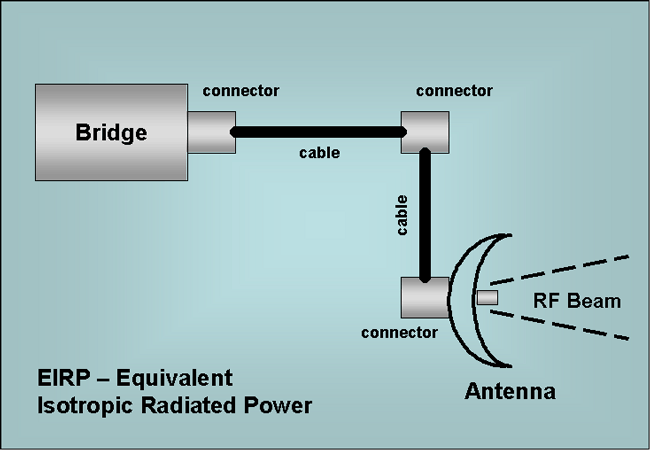
| For example, suppose the intentional radiator is
supplying 100 milliwatts to an antenna that passively amplifies the
energy due to focusing the power. Let's assume they are using
a 10 dBi antenna which amplifies the signal ten-fold. Then the
EIRP is 1000 mW or 1 Watt. The FCC regulates both the power output of the intentional radiator and the antenna element. |