Some Background on Antennas
|
Background. While it is
definitely a focus of Electrical Engineers to learn about and design
antennas, it really shouldn't be expected from students in Information
Systems. Yet, have some "bottom up" understanding of how antennas
operate and what sorts of characteristics relate to their proper and
improved function is important. This page, while entirely
superficial from an Electrical Engineer's point of view, should help
people who need to make decisions and perform implementations about
wireless gain insight into what are hopefully important characteristics. Some of the major things that a implementer or decision maker needs to be aware of in order to improve wireless function are the following.
In general, you can think of antennas as taking electrical energy and converting them into RF - Radio Frequency waves when transmitting. When receiving they convert RF waves into electrical energy. The shape, structure and length of particular aspects of antennas definitely impact their performance. We will discuss three basic types of antennas.
Notice how these classifications are based on how they transmit RF waves. We will start with omnidirectional antennas. Omnidirectional Antennas. Omnidirectional antennas radiate energy equally in all directions around the antenna's vertical axis. The most common type used for wireless LANs is called a dipole antenna. These are almost all one sees on APs - Access Points. A dipole antenna usually consists of multiple elements. The length of each of elements relates to the wavelength to which it is attuned. Remember, an antenna is most sensitive to to RF signals
A 2.4 GHz dipole antenna usually consists one or more 1/2 wavelength elements joined together. An element that is 1/2 wavelength at 2.4 GHz is approximately 2 inches in length. These elements are small when compared to the "rabbit ears" that used to be used for television reception because wavelengths in the 100 MHz TV spectrum are much longer. As the number of elements in a dipole antenna increases so does its gain. A dipole antenna's radiant energy is concentrated in a pattern that looks like a doughnut. The antenna sits vertically within the hole of the doughnut. The following image reflects a cutaway of the doughnut. |
| As the gain increases the antenna's range decreases along the vertical axis and reaches out further on the horizontal. This is illustrated in the following image. |
| These increases and decreases can be significant
enough to affect AP placement and effectiveness. It is
important to remember these sorts of radiation patterns when placing
antennas. You might actually place an antenna too high to
really reach users on the floor, or you might actually be pushing
through the floor to the next level much more than you want. Some dipole antennas actually come with a few degrees of downtilt built into their radiation patterns. This is designed to occur omnidirectionally so that you don't need to tilt the actual antennas and possibly use more than one antenna to get the desired coverage or undesired "backwash". When the total energy that is emitted by an antenna doesn't really increase, but the distribution becomes more or less focused, it is called passive gain. The gain is usually increased because a particular antenna design focuses more of its energy in a specific direction. Active gain is achieved through use of an amplifier. This sort of approach increases coverage without changing radiation patterns. Remember, when working with passive gain, the increases result in increased focus which can be disadvantageous. Semi-Directional Antennas. There are generally three main types of semi-directional antennas.
The patch and panel antennas are generally flat and designed for wall mounting. The yagi antennas are usually look like a cylinder with an antenna with tine inside. The following diagram represents a typical radiation pattern of a directional patch or panel antenna. |
| Notice how there is very little that
radiates out the back. A typical coverage area for a yagi antenna follows. |
| These are generally more directed than
the patch or panel antennas. In order to better describe the operating characteristics of these sorts of antennas we need to first define some concepts illustrated in the next image. |
| Beamwidth
is usually measured by measuring the number of degrees
off-axis where the beam drops to 1/2 its strength in the 0°
position. From this one can observe, through
collecting data, both a vertical and horizontal beamwidth. To get greater precision one needs to develop azimuth and elevation charts which are beyond the scope of this course. Now with these notions in mind, most patch or panel antennas focus coverage in a horizontal arc of 180° or less. This is also done with very little coverage behind the antenna. Yagi antennas are generally more focused with beamwidths around 30°. Though yagi antennas can sometimes reach beamwidths around 90°. The following table summarizes some typical beamwidth ranges for typical antennas. |
| Antenna Type | Horizontal Beamwidth | Vertical Beamwidth |
| Omnidirectional | 360° | ranges from 7° to 80° |
| Patch/Panel | ranges from 30° to 180° | ranges from 6° to 90° |
| Yagi | ranges from 30° to 78° | ranges from 14° to 64° |
| Parabolic Dish | ranges from 4° to 25° | ranges from 4° to 21° |
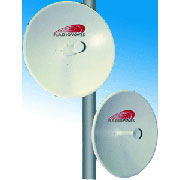
| Directional Antennas. These sorts of antennas are typically known to be used for wireless bridges between buildings over some distance. The following diagram represents a typical sort of coverage area. |
| While the radiation is quite directed it isn't
really a narrow beam like most people probably realize. There
are also some fairly weak radiation areas to the sides. There are usually two main types of antennas that fit this category.
The grid antennas are usually used because they are more stable in winds and other non "blue sky" events. |
 |
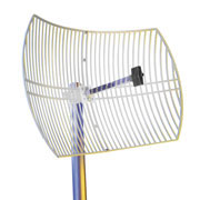 |
| Some Winncomm Parabolic Dish Antennas | A Proxim Grid Antenna |
| LOS - Visual Line of Sight is defined as the line from one directional antenna to the next. This line isn't generally as straight as people visualize it and there can be some illusion based on how light bends due to things like reflection, refraction and diffusion. This is illustrated in the following image. |
| But, you need to remember that RF doesn't travel
purely in a beam like a laser. So the effectiveness of a
connection can be impacted by blockage within something called the
Fresnel Zone. The next diagram illustrates the shape of the RF between two antennas. |
| But, unfortunately, the Fresnel Zone can be
viewed as the supporting structure for the wave and if it have too
much blockage then the RF can be unreliable, interrupted or even
ineffective. The next diagram illustrates how even trees can break up and/or absorb the signal. |
A standard rule of thumb is that as long as the
Fresnel Zone blockage is < 40% then the signal will be
acceptable. But, it is considered to be much more intelligent
to aim for 20% because things happen.
You also need to learn about other restrictions on these sorts of antennas due to things like FAA or FCC regulations. We will leave these off at present. Fresnel Zone Computations. Finally, we want to present some computations associated with the Fresnel Zone. There are a number of ways to guarantee we have less than 40% blockage. One of the most conservative is to guarantee that a particular radius that corresponds to 60% is entirely unobstructed. So the formula for the minimum clear radius around the LOS follows. |
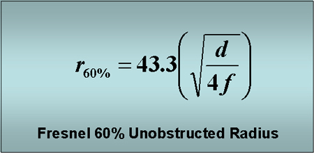
| If we have a distance of 5 miles between antennas and the signal is at the 2.4GHz frequency, we would get the following computation for the radius of the unobstructed zone. |
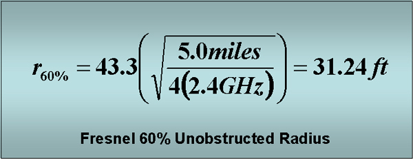
| This will adjust for km and meters. Though,
personally, I'd like to find a source that is more careful about the
units! Finally, the computation for the radius of the Fresnel Zone is done with the following formula. |
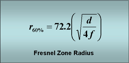
| Notice only the multiplicative constant changes. The last thing to notice, which is very surprising to me, is that these Fresnel Zone computations do not depend on the beamwidth of the signal. If the signal reaches, then it reaches! While there are other formulas that deal with things like earth bulge if the attempted link covers longer distances and different components of the Fresnel Zone, we will leave these out. Grounding and Lightning. It is almost surely self deceptive to think that you can place wireless antennas on tops of buildings and your perfect relationship with God will protect all that you do from "acts of God" such as lightning. Particularly if you are installing antennas outdoors, and even more so if you are installing them on a cell tower or mast, one needs to make sure that there are sufficient safeguards. It is likely to be important to hire a professional antenna installer. Grounding serves a number of purposes. A primary purpose is to provide a path of very little resistance for lightning to follow to get to the earth or ground. This is so that the lightning will not travel through the RF equipment. It is also important that the path not create much impedance/resistance since higher impedance helps create greater heat as the lightning grounds. You also need to make sure that all systems interconnected systems have a common ground so that surges will not cause voltage differentials within the system and cause enough current flow to damage equipment. Typical grounding systems require a grounding rod, a copper rod, be driven to a minimum depth of eight feet. Then equipment needs to be connected to this rod through low impedance grounding wires or straps. It can also be worthwhile to make use of lightning arrestors (diverters) if you are making use of coaxial cable to connect antennas. Coax cable can be subject to surges from nearby lightning strikes. These protect the network side of any connections to an antenna that may be struck. It can be useful to make sure you have arrestors that are reusable. Some designers also insert a short run of fiber optic cable between the wireless or network equipment and the antenna. |