Technology Review
Introduction.
Now we will engage in a brief review of technology as a preliminary to
designing networks. While giving as everyday language definitions
as possible, we categorize the basic device types of internetworking as
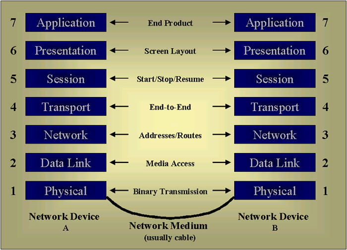
More about these will be said in individual pages that are also going to present some of the different products that are available. The internet infrastructure is essentially composed of millions of these sorts of devices loosely hooked together via a sophisticated global address system. Most often, twisted pair copper cabling is used to connect in the desktops and the big trunk lines run over high speed fiber optic cable. It is also the case that all of the preceding devices, except the interconnectives, are essentially computers of some sort in themselves in that they have CPUs, memory and operating systems. But they are designed to move data, not store it or present it so they don't have things like CRTs or disks. The OSI Reference Model. The OSI Reference Model or Open Systems Interconnection reference model is used to help make sure that systems all around the world can interconnect with each other. For example, getting an Ethernet LAN to transparently exchange messages with an IBM Token Ring LAN. The overall goal of this standard is to promote interoperability. It was used as the basis of the template for the IP or Internet Protocol. The OSI model divides operating in networks into seven functional layers. Each layer specifies the functions or set of functions to be performed when data is transferred across a network. Regardless of whether the local network operating system is Novell Netware, AppleTalk or IP if the operating system adheres to the OSI model more or less the same rules are applied at each layer. A diagram of the OSI model is given in the following image. |
| Each of the layers is essential a protocol associated
with stack of how to handle data at its layer. The model causes
the data to add on or peel off the necessary information at each layer
depending on whether the data is being sent or received.
The following table gives a succinct presentation of the function of each layer. |
|
Layer |
Description |
| Physical Layer | This layer is responsible for the
transmission of the bit stream. When sending, it accepts frames
from the Data Link Layer and transmits their structure and content
serially, one bit at a time.
It is also responsible for the reception of data, one bit at a time. These streams are then passed up to the Data Link Layer for reframing. This layer doesn't do anything to determine the significance of what is moving. It's solely concerned with the physical characteristics of electrical and/or optical signals. The Physical Layer label can be misleading, it doesn't actually refer to the transmission media itself! |
| Data Link Layer | When transmitting this layer is responsible
for packing instructions, data and so on into frames. The frame
must also contain a way to verify the integrity of its contents upon
delivery. Appropriate messages must be sent.
When receiving it is also responsible for reassembling any binary streams received from the Physical Layer back into frames. Though, it isn't really rebuilding the frame, it's buffering the incoming stream until it has complete frames. |
| Network Layer | This layer establishes the route to be used between the origin and destination computers. It doesn't so any sort of error detection/correction. It is used to establish communications with systems that lie beyond the local LAN segment. It has its own routing addressing architecture which is separate and distinct from Data Link Layer machine addressing. This layer is required only if the computers exist on different network segments separated by a router. |
| Transport Layer | This layer is responsible for the
end-to-end integrity of transmissions. This layer provides this
function beyond the local LAN segment. It can detect packets that
are discarded by routers and automatically send a retransmit request.
When receiving, this layer also resequences packets that have arrived out of order. This layer is capable of determining the original sequence of packets and put them back into that order before passing them back up to the Session Layer. |
| Session Layer | This layer is often unused as a separate
layer. Many protocols bundle this layer's functionality into the
Transport Layer's.
The function of this layer is to manage the flow of communications during a connection between two computer systems. |
| Presentation Layer | This layer manages the way data is encoded. |
| Application Layer | This layer provides the interface between the application and the network's services. This layer can be thought of as the reason for initiating the communications session. For example, FTPing some files to a server. |
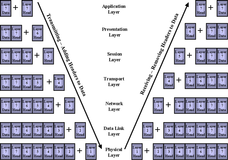
| In order to communicate, two systems must pass data,
instructions, addresses and whatever between the layers. Although
communications flow vertically through the stack of layers, each layer
functions as if it is communicating directly with its counterpart layer
on remote computers.
To create this logical adjacency of the layers, each layer of the original computer's protocol stack adds a header. This header can be used only by that layer or its counterparts on other computers. The receiving computer's protocol stack removes headers, one layer at a time as the data is passed up to the application. The following diagram helps represent this. |
|
|
| This starts to give you some sense of how these
communications are executed. While there is a lot of jargon and
meaning, eventually it coalesces.
The following diagram represents how packets operate on routed wide area networks, frames operate within local area network segments and signals operate across the physical media |
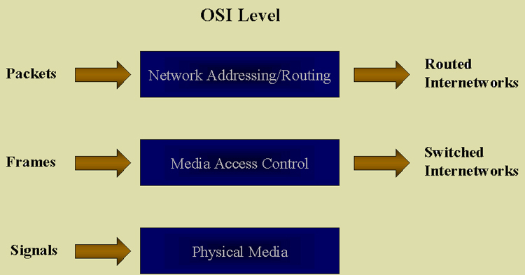
| Then the next three pages after this page will go into much more detail about technologies and specifications for physical transmission media, LANs and WANs. These correspond to the functions three layers of the OSI Reference Model displayed above. Remember, the OSI Reference Model is a protocol stack, even the physical layer is not really all that physical. But rather than dig into the OSI Model further we will focus on the more physical aspects that underlie these layers. |