Interconnectives - Transmission Media
| Introduction.
For lack of a better word I have decided to refer to the physical or
not-so-physical transmission media as interconnectives.
Remember, these connections are made via a large range of
electromagnetic wave frequencies using "wires" or
"wireless". An electromagnetic
wave is the physical form of energy described by the
electromagnetic spectrum. The spectrum starts at zero
oscillations, rises through the range of frequencies that can be
perceived by human senses through the various forms of light, up to the
frequencies called X-rays and gamma rays.
The rates of frequency are measured in Hz - Hertz. This is directly related to the wavelength, which can vary from billionths of a meter to several meters. For whatever reasons, Hz are usually used for lower frequency bands and wavelengths are usually used when talking about higher frequency phenomena such as light. The standard names and ranges/bands are given in the following diagram. |
Notice how the visible range is very very small.
We now need to quickly define a few terms which you have hopefully seen
before.
Now we need to state one basic principle.
The following tables contain some of the most important signal characteristics for low and high frequencies. |
| Low Frequencies |
| persistent signal |
| more durable |
| more penetrating |
| less frangible |
| FCC regulated due to the above |
| low bandwidth |
| broad radiation |
| High Frequencies |
| more frangible |
| high bandwidth |
| potential for tightly focused transmission |
|
For example, light doesn't penetrate even the slimmest of opaque materials. But it is very capable of transmitting data at high rates. Radio waves tend to be rather omni-directional, but not very frangible. We will make use of these concepts to compare different transmission media. Now we will start to describe different transmission media. We will split this into two sections, one for wired, the other for wireless. |
Wired Transmission Media
We will survey the following wired transmission media
Coaxial Cable. Coaxial cable, usually referred to as coax, is named because it has two concentric conductors separated by insulation. The two conductors have the same axis. The following diagram illustrates the standard configuration. |
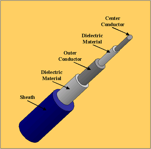
| Coax cables may look the same but they can have very
different levels of impedance. For example, the 10Base2
Ethernet coax cabling has 50 ohm impedance in a wire that's
three-eighths of an inch in diameter. This provides 10Mbps signal
speed for up to 185 meters.
Two of the biggest advantages of coax are that it can support high bandwidth communications over relatively long runs without repeaters or hubs. Coax was the original transmission media specified for Ethernet. Since then it has become almost completely supplanted by some form of twisted pair wiring. The main reasons for this are coax is a relatively fragile cable that does not suffer kinks, severe bends or crushing pressure very well. Any of these can inhibit performance significantly. Other major reasons for this supplanting are due to coax's cost and size. It is more expensive than twisted pair and it takes up much more space in cable ducts, raceways and whatever. Currently, coax is generally used only for bringing broadband cable TV signals to subscribers. Twisted Pair Wire. Twisted pair wiring has been used to support voice communications for quite a long time. It has become the pervasive media used for LANs. Twisted pair wiring makes use of two relatively thin wires, 18 to 24 American Wire Gauge, from 0.016 to 0.035 inches in diameter. The wires are coated and spiraled around each other. The twisting helps cancel out electromagnetic interference. The gauge or thickness of the wire is highly related to its performance. Thicker wires translate it to greater capability to handle greater bandwidth. Unfortunately, as gauge increases so does attenuation. Twisted pair wiring comes in a large variety that range from a single pair of voice grade wires to 600-pair trunk cables. Some other features that can be modified to improve performance are
For LANs, four pairs of twisted pair wires are usually bundled in a sheathing. The following image represents a shielded bundling with more than four pairs. |
|
The two main types of twisted pair are shielded and unshielded. Shielded twisted pair -STP uses an extra layer of foil or braided metallic wire directly below the sheathing. While the extra shielding helps prevent extraneous noise from being inducted into the wiring, it also increases self-impedance. Certain radiation that would naturally occur without he shielding is bounced back through the signal and significantly increases attenuation and is usually more detrimental than beneficial. Unshielded twisted pair - UTP is much more common. Four pair UTP makes use of eight wires or leads separated into groups of two. One way these are often used is that one pair supports transmission and another pair supports reception. The other wires aren't used in most LANs. But for those that operate at speeds of 100Mbps or higher all four pairs are used. Twisted pair is a commodity and is very likely to have consistent performance regardless of the manufacturer. UTP is classified by categories of performance by their function. Manufacturers have to prove compliance with certain standards. Originally, there were five benchmark categories numbered one through five. Over time, the market has coalesced into two viable performance levels, Cat-3 and Cat-5. Cat-6 and Cat-7 have been added but at present they are still very expensive. Category 3 UTP offers 16MHz of bandwidth which translates to 10Mbps for up to 100 meters. Category 5 can support up to 100MHz of bandwidth . Depending on the distance limitations and LAN architecture, this can provide 100Mbps, 155Mbps or up to 256Mbps. Unfortunately, as maximum speed increases, maximum distance decreases. Fiber Optic Cable. Fiber optic cables can carry the higher frequencies of the electromagnetic spectrum. There is a huge variety of fiber optic cabling and it seems the only universal characteristics are
The extent of attenuation over distance varies according to the wavelength of the light and to the composition of the fiber. Fiber optic cabling is used in pairs, one for transmission, the other for reception. Fibers are usually described with a pair of numbers FiberDiameter/CladdingDiameter. For example, one extremely common LAN fiber is known as 62.5/125 micron glass. Light can either radiate outwards, as in a candle, or be focused directionally as done in flashlights. But even focused light is subject to some dispersion, think of flashlight beams as they get further from the source. There are two types of fiber optic transmission
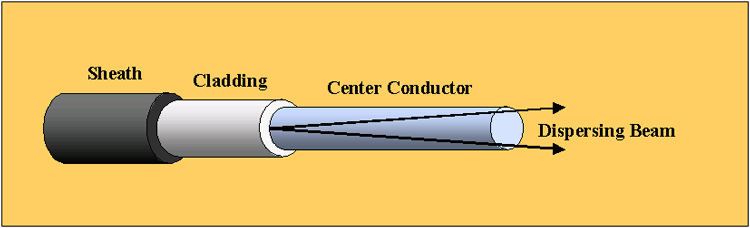
Multimode transmissions are driven by a light emitting diode (LED). LEDs sit at the lower end of the light spectrum do they have relatively lower bandwidth potential when compared to other light sources but they are relatively less expensive. An LED is not a very concentrated light source and as such requires a fairly wide transmission path. This rate of dispersion imposes practical limitations on the effective distance of LED driven fiber optic cable. The following diagram represents this dispersion. |
| Over distance, this dispersion results in some LED beam impacting the inside wall of the glass media. When this happens, the impact is at a shallow angle and the light does not escape into the cladding. The reflections puts the dispersed beams in a collision course with the remaining axial transmission. The following diagram represents this. |

| Thus, multimode beams are subject to attenuation due to
these photonic collisions. Also, the original signal will arrive
before the multiple reflections.
Multiple transmission modes can also be caused by improper terminations of the fiber optic cable and/or poor connections to the hardware. Non-concentric terminations result in dispersion. Even though some hardware takes advantage of multimodal dispersion it can get out of hand. While we have spent a lot of effort to present the things that can go wrong with multimodal transmissions, they still have some advantages, primarily the cabling and hardware that drive it are less expensive than for single mode. It is also the case that it is easier to wok with when compared to single mode fiber optic cabling because it is several times larger. Single mode fiber makes use of an Injection Laser Diode - (ILD). Lasers are well known for their highly concentrated beams. This beam still disperses, but quite negligibly over distances associated with LANs. Even at the outer limits of its effective range the beam still does not contact the inside walls of the fiber. The transmission remains well aligned within the center axis of glass. It reaches its destination in a single mode all at once. Single mode fibers are usually 5 or 10 microns with 125 micron classing. The costs of the fiber and laser hardware make this more of a commercial grade infrastructure technology than a LAN technology. There is tremendous available bandwidth. It is usually used in commercial telephone networks. |
Wireless Transmission Media
Networks that use unguided transmissions to transport data
and protocols have some to be known as wireless. It is important to
remember that the name wireless is really misleading. The vast
majority of purported wireless LANs still have some wiring for connections
someplace in the LAN. It is probably reasonable to classify wireless
LANs by identifying the following four characteristics.
The four main wireless interconnective technologies we will discuss are
Spread Spectrum Radio. The FCC has allocated the 902 - 928MHz and 2.4 - 2.4835GHz bands of the electromagnetic spectrum for industrial, scientific and medical (ISM) use. They are referred to as the ISM bands. The uses of these bands is largely unregulated except to establish guidelines for electrical and electronic devices that use these bands. Now for some definitions that relate to different strategies to make use of these bands. Baseband transmissions use the entire available bandwidth as a single channel. The same signal is sent across the entire band completely filling the available "pipe". Broadband transmissions channelize the available bandwidth into multiple, smaller channels where each smaller channel supports a different signal transmission. Frequency hopping also subdivides the bandwidth into multiple channels that are each used one-at-a-time to support signal transmissions. But with frequency hopping the signal hops from channel to channel at a predetermined rate and in a predetermined sequence. Frequency hopping has several advantages
In contrast, direct sequence uses the available channels sequentially. Each of these options has its advantages and disadvantages. Fortunately, these ISM bands provide sufficient bandwidth to compete with wire based LANs. They also tend to be relatively inexpensive since bands are not licensed and manufacturers can provide hardware for less money than they can for dedicated frequency products. Unfortunately, radio signals are not capable to full-duplex communication on a single frequency, you are either sending or receiving, but not both simultaneously. For example, think of walkie-talkies and the push to talk necessities. This and other complexities reduce the overall effective throughputs rate to 2Mbps in Ethernet compatible networking. Effective throughputs in wire based Ethernets is 5 to 5.5 Mbps. Thus, radio based connectivity could easily be a relative bottleneck in current networking environments. In addition, the absence of FCC licensing to give dedicated frequencies requires limiting wattage so that reach is somewhere between 600 and 800 feet. There are also other issues of competition for this range within zones that may greatly reduce its effectiveness. Single Band Radio. Single band radio is essentially the opposite of spread spectrum and uses a single channel. This signal is usually sent in the microwave range which are actually high frequency radio waves. Waves at the lower end of the microwave range behave much like radio waves, at the high end they behave much more like light. To use a dedicated frequency you need FCC licensing. This technology was pioneered by Motorola who obtained exclusive rights to the 18 - 19 GHz band for all the major metropolitan markets in the US. Motorola acts as an agent to the FCC for any customers wanting to use this technology. Firms that make sue of this maintain their existing wire based LAN backbones, hubs and software drivers. Transmission voltage is approximately 25 milliwatts which is too low to cause health concerns in metropolitan areas. The wattage, in conjunction with the relatively frangible microwave signal, limits the effective range to 140 feet of open air and 40 feet with sheetrock wall obstructions. The gross bandwidth is approximately 15Mbps. Modifying this due to typical Ethernet considerations reduces the effective yield to around 5.5Mbps, comparable to wired Ethernet LANs. Infrared. The infrared spectrum operates between the visible part of the electromagnetic spectrum and the shortest microwaves. Infrared is actually a form of light which cannot penetrate opaque solids but does reflect off them. Infrared can be used in direct and/or diffuse form. Direct infrared is typically used in household electronics with remote control devices which must be pointed at the device to be controlled. This is the same when applied to LANs. There has to be a line-of-sight connection. Diffuse infrared scatters omnidirectionally. The intent is to bounce signals off ceilings and walls so that the transmit/receive device doesn't need to be in line-of-sight. Infrared communications are not capable of penetrating even the least dense of opaque solids and thus don't require FCC regulation. But the FCC establishes specifications about the devices using the infrared spectrum. Lin-of-sight communications are severely limiting in most environments, particularly offices. Thus in offices, diffuse infrared is necessarily preferred to direct. But considering the highly frangible nature of the medium the effective range is extremely small, less than 100 feet. In addition the throughput rates are extremely modest. Laser. You can think of laser communications within a LAN as single mode fiber optic communication without the fiber optic. The cost precludes its use on a station by station basis. It's better when applied in ways similar to direct infrared. Essentially, it is best used to interconnect access units that are connected in some other way to stations. They are best when mounted away from people, as near to the ceiling as possible. This makes them much less likely to cause eye injuries or to be disrupted. They can also be used to bridge gaps such as parking lots. This sort of implementation usually costs less than paying for routers and leased lines. |