Interconnectives - Wire Based Transmission Media
| Introduction. For lack of a better word I have decided to refer to the physical or not-so-physical transmission media as interconnectives. This page will focus on wire based media. |
Wired Transmission Media
We will survey the following wired transmission media
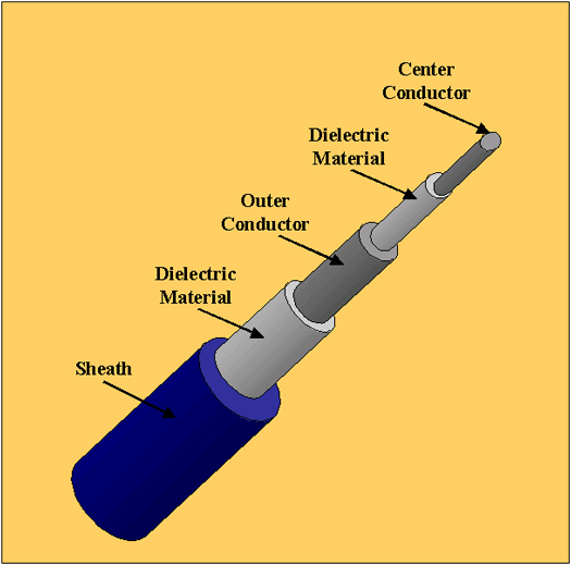
Coaxial Cable. Coaxial cable, usually referred to as coax, is named because it has two concentric conductors separated by insulation. The two conductors have the same axis. The following diagram illustrates the standard configuration. |
| The conductive material at both levels is copper.
The signals travel on the copper which receives additional protection from
the dielectric material. Two of the biggest advantages of coax are that it can support high bandwidth communications over relatively long runs without repeaters or hubs. Coax was the original transmission media specified for Ethernet. Since then it has become almost completely supplanted by some form of twisted pair wiring. The main reasons for this are coax is a relatively fragile cable that does not suffer kinks, severe bends or crushing pressure very well. Any of these can inhibit performance significantly. Other major reasons for this supplanting are due to coax' cost and size. It is more expensive than twisted pair and it takes up much more space in cable ducts, raceways and whatever. Currently, coax is generally used only for bringing broadband cable TV signals to subscribers. Coax cables may look the same but they can have very different levels of impedance. For example, the 10Base2 Ethernet coax cabling has 50 ohm impedance in a wire that's three-eighths of an inch in diameter. This provides 10Mbps signal speed for up to 185 meters. The following table contains a survey of the coax cabling you are most likely to encounter when working with LAN networking. |
| Designation | Common Name | Description | Network Use |
| RG-8 RG-11 |
Thicknet | One half inch diameter thick coaxial cable | 10Base5 |
| RG-58 A/U | Thinnet | One quarter inch diameter thin coaxial cable | 10Base2 |
| RG-58 C/U | Thinnet (military) | One quarter inch diameter thin coaxial cable | 10Base2 (military) |
| RG-62 | ARCnet | Thin coaxial cable | ARCnet networks |
| Coax cabling is standardized throughout the industry
according to RG - Registered Grade
specifications. Of the hundreds of grades in existence, only a very
few are used for LANs. Military grade cabling has a slightly thicker
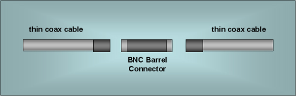
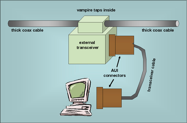
outer covering contributing to its resistance to outside influences. Sometimes the internal copper wiring has a solid core, other times it is stranded. The thicker cabling has much greater transmission capabilities as we've seen in other web pages. Thicknet cabling requires more complicated devices than thinnet to make connections. A vampire tap must be used to drill into the core of the thicknet cable. For thinnet a BNC or T connector can be used. The following diagram represents a BNC connector for thinnet. |
| This diagram represents using an AUI connector for thicknet. |
| Twisted Pair Wire.
Twisted pair wiring has been used to support voice communications for
quite a long time. It has become the pervasive media used for
LANs. Twisted pair wiring makes use of two relatively thin wires,
18 to 24 American Wire Gauge, from 0.016 to 0.035 inches in
diameter. The wires are coated and spiraled around each
other. The twisting helps cancel out electromagnetic
interference. The gauge or thickness of the wire is highly related
to its performance. Thicker wires translate it to greater
capability to handle greater bandwidth. Unfortunately, as gauge
increases so does attenuation. Twisted pair wiring comes in a large variety that range from a single pair of voice grade wires to 600-pair trunk cables. Some other features that can be modified to improve performance are
For LANs, four pairs of twisted pair wires are usually bundled in a sheathing. The following image represents a shielded bundling with more than four pairs. |
|
The two main types of twisted pair are shielded and unshielded. Shielded twisted pair -STP uses an extra layer of foil or braided metallic wire directly below the sheathing. While the extra shielding helps prevent extraneous noise from being inducted into the wiring, it also increases self-impedance. Certain radiation that would naturally occur without he shielding is bounced back through the signal and significantly increases attenuation and is usually more detrimental than beneficial. Unshielded twisted pair - UTP is much more common. Four pair UTP makes use of eight wires or leads separated into groups of two. One way these are often used is that one pair supports transmission and another pair supports reception. The other wires aren't used in most LANs. But for those that operate at speeds of 100Mbps or higher all four pairs are used. UTP in cabling is popular for a number of reasons such as the following.
STP has extra shielding that helps reduce the impact of outside interference. But it is more expensive and generally not able to span distance as great as UTP due to extra impedance. STP is often used in AppleTalk and IBM networking solutions. Twisted pair is a commodity and is very likely to have consistent performance regardless of the manufacturer. UTP is classified by categories of performance by their function. Manufacturers have to prove compliance with certain standards. Originally, there were five benchmark categories numbered one through five. Over time, the market has coalesced into two viable performance levels, Cat-3 and Cat-5. Cat-6 and Cat-7 have been added but at present they are still very expensive. Category 3 UTP offers 16MHz of bandwidth which translates to 10Mbps for up to 100 meters. Category 5 can support up to 100MHz of bandwidth . Depending on the distance limitations and LAN architecture, this can provide 100Mbps, 155Mbps or up to 256Mbps. Unfortunately, as maximum speed increases, maximum distance decreases. Fiber Optic Cable. Fiber optic cables can carry the higher frequencies of the electromagnetic spectrum. There is a huge variety of fiber optic cabling and it seems the only universal characteristics are
The extent of attenuation over distance varies according to the wavelength of the light and to the composition of the fiber. Fiber optic cabling is used in pairs, one for transmission, the other for reception. Fibers are usually described with a pair of numbers FiberDiameter/CladdingDiameter. For example, one extremely common LAN fiber is known as 62.5/125 micron glass. Light can either radiate outwards, as in a candle, or be focused directionally as done in flashlights. But even focused light is subject to some dispersion, think of flashlight beams as they get further from the source. There are two types of fiber optic transmission
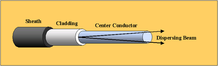
Multimode transmissions are driven by a light emitting diode (LED). LEDs sit at the lower end of the light spectrum do they have relatively lower bandwidth potential when compared to other light sources but they are relatively less expensive. An LED is not a very concentrated light source and as such requires a fairly wide transmission path. This rate of dispersion imposes practical limitations on the effective distance of LED driven fiber optic cable. The following diagram represents this dispersion. |
| Over distance, this dispersion results in some LED beam impacting the inside wall of the glass media. When this happens, the impact is at a shallow angle and the light does not escape into the cladding. The reflections puts the dispersed beams in a collision course with the remaining axial transmission. The following diagram represents this. |
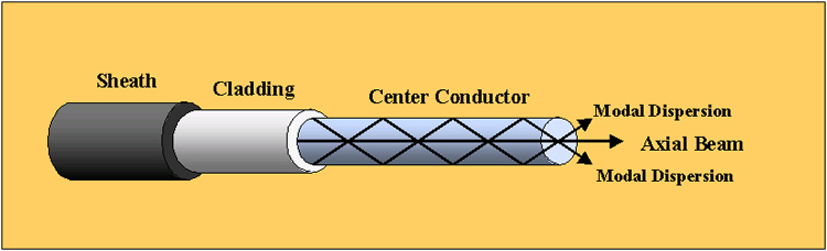
| Thus, multimode beams are subject to attenuation due to
these photonic collisions. Also, the original signal will arrive
before the multiple reflections.
Multiple transmission modes can also be caused by improper terminations of the fiber optic cable and/or poor connections to the hardware. Non-concentric terminations result in dispersion. Even though some hardware takes advantage of multimodal dispersion it can get out of hand. While we have spent a lot of effort to present the things that can go wrong with multimodal transmissions, they still have some advantages, primarily the cabling and hardware that drive it are less expensive than for single mode. It is also the case that it is easier to wok with when compared to single mode fiber optic cabling because it is several times larger. Single mode fiber makes use of an Injection Laser Diode - (ILD). Lasers are well known for their highly concentrated beams. This beam still disperses, but quite negligibly over distances associated with LANs. Even at the outer limits of its effective range the beam still does not contact the inside walls of the fiber. The transmission remains well aligned within the center axis of glass. It reaches its destination in a single mode all at once. Single mode fibers are usually 5 or 10 microns with 125 micron classing. The costs of the fiber and laser hardware make this more of a commercial grade infrastructure technology than a LAN technology. There is tremendous available bandwidth. It is usually used in commercial telephone networks. |