Some More on Ethernet
| Introduction.
Now we will present some more information on Ethernet.
We will present two main sections. One on the structure of Ethernet
frames. The second presents more on how things actually work on
Ethernets and some of their limitations. Frame Structure. The overall package containing data is called a frame in Ethernet parlance. Frames are developed at Layer 2, the Data Link Layer, of the OSI model. These are much of the basis for the packets that travel the Internet. Each frame contains
Last I knew there were four different frame types.
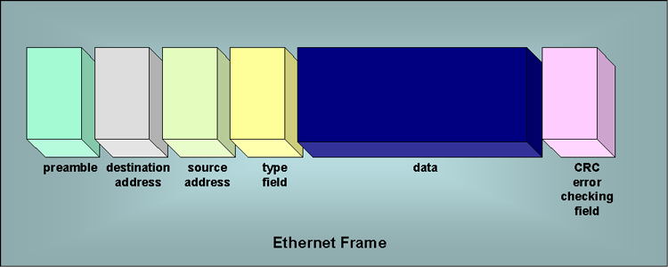
The two that are generally used on TCP/IP networks are Ethernet_II and Ethernet_SNAP. The following diagram represents the basic structure of an Ethernet II frame type. |
The fields are described a bit in the following outline
Rules of Engagement. There are two important rules of engagement that almost always need to be followed in order to get an Ethernet to function in desirable ways. But first we need a definition, a collision domain, is a segment of a network in which messages will collide if two devices transmit at the same time.
How does the 5 - 4 - 3 rule apply to twisted pair networks? Many sources claim it is inappropriate to apply this rule to twisted pair networks. Littlejohn Shinder states that one needs to apply the rule to twisted pair networks but in a slightly different fashion.
Fortunately, we can create much larger Ethernet networks by using switches and routers to connect collision domains. We'll get into how switches can be used to manage collisions and largely get rid of collision domains in future sections. 10BaseT Node Capacity. The number of nodes per segment on a twisted pair star wired bus is exactly two. This the computer or device at one end and the hub at the other. The maximum number of nodes in a hub based network should not exceed 100 because of the exponential growth in the number of collisions after 100 nodes for 50 devices. Some sources claim the number of devices shouldn't exceed 40. These limits can be extended by using devices that make better use of available bandwidth such as switches. But these limits obviously depend on the traffic intensities created by using the devices. |